Wednesday, October 19, 2005
Engine Mounts...
Spent some time this evening aligning the engine within the chassis - took a while to get it perfectly square. Then fabricated the right engine mount and tack welded it in position. Photos to follow...

Tuesday, October 18, 2005
Progress again
Decided to junk the subframe from the donor car. After a little work, it was off - when we tried to move it we discovered that it was bl***y heavy - good decision I think! The rear of the car was the next part to be fabricated and welded on - looks great. A day at the Donington show yielded lots of useful info chatting to people, and lots of goodies from the various stands, although my plans to buy suspension brackets from MK were foiled - they forgot them! This evening has seen the creation of the strut brackets and part of the engine mounts. All in all, a good weeks work!
Friday, October 07, 2005
Stripping the donor car - again

The new donor car has been delivered - a 1996 Fiesta 1.25. Stripping this car was much easier than the Rover. After an hour and a half, all the under bonnet connections were undone. Removal of the subframe mounting bolts was east, it was then a case of removing the engine mounts and the strut top mounts. A minor delay occured whilst searching for an 18mm ring spanner - remarkably elusive!!! The engine was then lowered onto a low trolley under the car. The front of the car was then lifted on the engine hoist and the tiny, all aluminium engine and gearbox wheeled out. The engine is now resting in the chassis awaiting construction of the engine and suspension mounts, while the donor car awaits the removal of all the ancillaries to make the engine run. Photos to follow...
Monday, September 19, 2005
Top Tip Three-Measure Twice, cut once...
I wanna tell you a story....
When the build began, I understood that Mini's and Metro's had a 4"PCD (diagonal distance between wheel studs). When I was offered the Rover, I measured the PCD - 4" - great, I'll use Metro front hubs.
I duly sourced front hubs from a low mileage Rover Metro, put them in the corner of the workshop and forgot about them....
Big Mistake!!!!
A chance conversation with a 'Font of automotive knowledge' (whose Mastermind specialist subject is 'PCD's from 1872 to the present day') set me on edge. To the workshop.....
What we found:
1. The 'Rover' Metro uses a PCD of 95.6mm, unlike its A series predecessor.
2. the Rover 200/400 uses a PCD of 100mm, not 4" (101.6mm).
So nothing fits anything. B****x.
After long deliberation of the options, the difficult decision to ditch the Rover was made. Using a Rover Metro front subframe at the back was briefly considered but with the future supply of Rover parts in the balance, Uncle Henry's parts bin called.
The local tame scrappy is very keen to use my engine in his Banger racing car, so has offered me a deal on a Zetec-s engined Fiesta 1.25. This is a light, revvy engine that will fit in the chassis with no modifications. It also allows the use of standard 'Locost' suspension with Cortina Hubs at the front.
Stay tuned for 'Stripping the Donor part deux'...........
When the build began, I understood that Mini's and Metro's had a 4"PCD (diagonal distance between wheel studs). When I was offered the Rover, I measured the PCD - 4" - great, I'll use Metro front hubs.
I duly sourced front hubs from a low mileage Rover Metro, put them in the corner of the workshop and forgot about them....
Big Mistake!!!!
A chance conversation with a 'Font of automotive knowledge' (whose Mastermind specialist subject is 'PCD's from 1872 to the present day') set me on edge. To the workshop.....
What we found:
1. The 'Rover' Metro uses a PCD of 95.6mm, unlike its A series predecessor.
2. the Rover 200/400 uses a PCD of 100mm, not 4" (101.6mm).
So nothing fits anything. B****x.
After long deliberation of the options, the difficult decision to ditch the Rover was made. Using a Rover Metro front subframe at the back was briefly considered but with the future supply of Rover parts in the balance, Uncle Henry's parts bin called.
The local tame scrappy is very keen to use my engine in his Banger racing car, so has offered me a deal on a Zetec-s engined Fiesta 1.25. This is a light, revvy engine that will fit in the chassis with no modifications. It also allows the use of standard 'Locost' suspension with Cortina Hubs at the front.
Stay tuned for 'Stripping the Donor part deux'...........
Catch up on the build so far
Building the Space frame
Step 1 was to purchase a sheet of 18mm MDF to use as a jig for the frames. The upper and lower planform were marked and holes drilled either side to accept a length of threaded rod. The cut tubes were put in place and clamped to the board using offcuts of plywood. This ensured that there was no distortion during the welding process. We then spent some time learning to weld, and here is the first Top Tip – MiG welding works MUCH better if you have gas in the bottle……..nuff said?


The top and bottom frames were then accurately positioned using a precision jig and the corner uprights cut to fit. Some time was spent ensuring an accurate fit prior to welding. As this was the first angled weld, a test piece was welded first – eventually with good results. However, when I tried on the chassis, it was awful! Nothing for it but to grind it off and start again. And again…Returning home in a foul mood, I kicked the cat and went to bed. Next day, same settings, nothing changed produced decent results. Doh!
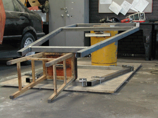

After the considerable effort cutting the uprights, for the diagonals we used a long length of paper to prototype the tube. This was wrapped around the tube then marked and cut. This gave excellent results with a good fit virtually straight away. Top Tip Two – Paper is SO much easier to cut than steel!

Step 1 was to purchase a sheet of 18mm MDF to use as a jig for the frames. The upper and lower planform were marked and holes drilled either side to accept a length of threaded rod. The cut tubes were put in place and clamped to the board using offcuts of plywood. This ensured that there was no distortion during the welding process. We then spent some time learning to weld, and here is the first Top Tip – MiG welding works MUCH better if you have gas in the bottle……..nuff said?


The top and bottom frames were then accurately positioned using a precision jig and the corner uprights cut to fit. Some time was spent ensuring an accurate fit prior to welding. As this was the first angled weld, a test piece was welded first – eventually with good results. However, when I tried on the chassis, it was awful! Nothing for it but to grind it off and start again. And again…Returning home in a foul mood, I kicked the cat and went to bed. Next day, same settings, nothing changed produced decent results. Doh!


After the considerable effort cutting the uprights, for the diagonals we used a long length of paper to prototype the tube. This was wrapped around the tube then marked and cut. This gave excellent results with a good fit virtually straight away. Top Tip Two – Paper is SO much easier to cut than steel!

This is what we are building!
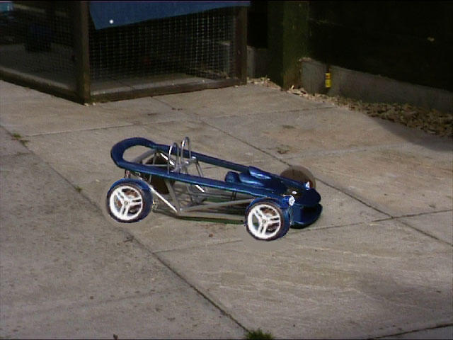
Here is a quick picture of a MODEL of the Mistrale. It is not a full size car on giant slabs!
Sunday, September 11, 2005
Stripping the Donor Car
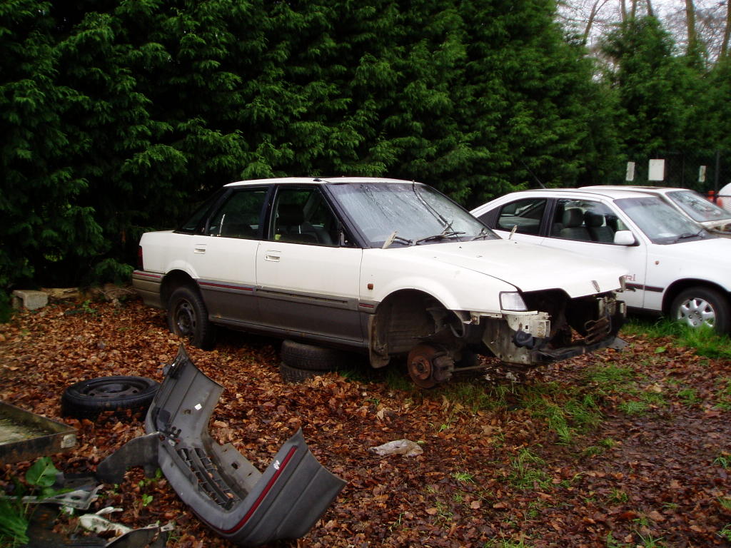
The donor car was a 1990 Rover 416GTi that was purchased from a friend for the princely sum of £10. It had failed its MoT because of a small area of rust next to a suspension mount - no problem to fix once removed from the car! Other that this, the car had had much attention and money lavished upon it including nearly new back brakes.
The first evening was a bit like a feeding frenzy. With the help of two friends, most of the under bonnet connections were undone, along with the front crossmember - all of this taking about an hour. We decided to strip the car outside to ease disposal of the bodyworf once it had no wheels. On the second night, working alone, I disconnected the steering column, pedals and gearchange - again about an hour before the light faded. On the final night, a friend helped lift the front of the car with an engine hoist, and prop it up. A trolley was then wheeled under the engine and gear box. The final mounts were undone and the car lifted off the engine/trolley assembly!

We then returned to remove various other parts from the car. The back axle and rear uprights were removed as a complete unit - in case anything proved useful! Next followed the fuel tank, filller neck and the remains of the exhaust. The wiring loom followed after a very hot evening of work and finally, an angle grinder was taken to remove the thick walled bushed that the two fornt cross members bolted into. The full leather interior had already been removed and has been put aside - if it is not used, e-bay calls!
Subscribe to:
Posts (Atom)